The selection of airfoils is paramount for the design of an aircraft.
Intro:
An airfoil (or aerofoil) is a shape designed to generate lift when air flows over it, commonly used in the wings, blades, or other surfaces of aircraft, helicopters, wind turbines, and propellers. The airfoil’s unique shape allows it to create a difference in air pressure between its upper and lower surfaces, enabling flight or other aerodynamic functions.
Key Components of an Airfoil:
- Leading Edge:
The front part of the airfoil where airflow first meets the surface.
- Trailing Edge:
The rear part of the airfoil where the airflow from the upper and lower surfaces meets.
- Chord Line:
An imaginary straight line drawn from the leading edge to the trailing edge of the airfoil.
- Camber:
The curvature of the airfoil. The more cambered the surface, the greater the potential lift. Airfoils can be symmetric (no camber) or asymmetric.
- Upper Surface:
The top part of the airfoil, usually more curved, which causes the airflow to move faster, lowering the pressure.
- Lower Surface:
The bottom part of the airfoil, typically flatter, which experiences slower airflow and higher pressure.
Here are some common types of airfoils that need to be compared according to the UAV design scenario:
Symmetric:
Symmetrical airfoils have identical upper and lower surfaces. They are suited to rotary-wing applications because they have almost no center of pressure travel. Travel remains relatively constant under varying angles of attack, affording the best lift-drag ratios for the full range of velocities from rotor blade root to tip. However, the symmetrical airfoil produces less lift than a nonsymmetrical airfoil and also has relatively undesirable stall characteristics.
Asymmetric:
The advantages of the asymmetrical airfoil are increased lift-drag ratios and more desirable stall characteristics. Nonsymmetrical airfoils were not used in earlier helicopters because the center of pressure location moved too much when angle of attack was changed.
“S” shaped:
This type of wing shape usually features a tortuous chamber line. The aerodynamic effects of this design the most stable one among all four airfoils. Regardless its positive Cm in any flight condition, the “S” shaped wing’s performance is mediocre in all AOA intervals.
Supercritical airfoils:
A supercritical airfoil is an airfoil that, principally, has been designed to delay the onset of wave drag in the transonic speed range. More advantage includes the potential for more efficient wing design as the supercritical airfoil allows for a reduction in wing sweep or an increase in wing thickness without the corresponding increase in wave drag that would be associated with a typical airfoil.
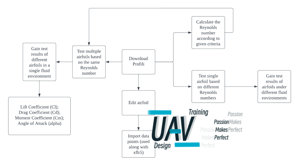
The software Profili is often used when doing the comparison of airfoil performances. Here is the workflow of Profili testing:
Take this figure as an example, this is the test result of 4 different airfoils under the same fluid environment: when the Reynolds number is 249000.
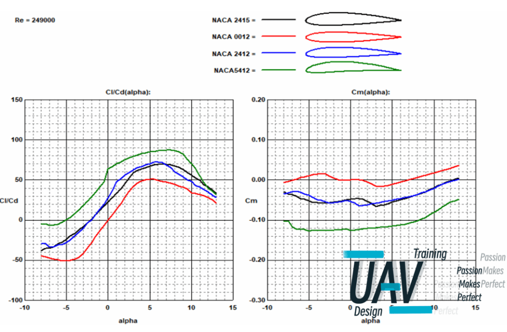
On the left, is the lift-drag ratio map; on the right, is the moment coefficient map.
- In the range of appropriate flight Angle of Attack (AoA) (0-10 degrees), the larger the lift-drag ratio, the better the aerodynamic performance.
- In the range of appropriate flight Angle of Attack (AoA) (0-10 degrees), the closer Cm is to 0, the more stable it is (the Cm of the tail should be as small as possible).
As for polar curve maps, take this as an example, this is the comparison of 2 airfoils when Reynolds number is 310000.
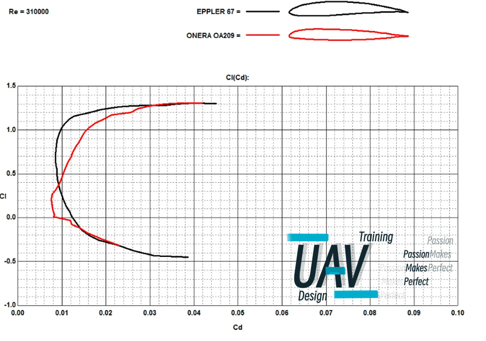
- The Cl corresponding to the leftmost end of the polar curve is the most suitable Cl for the airfoil.
For Chinese users, here are some useful videos:
安装软件
【【保姆级教程】Profili软件安装及汉化教程!!!】 https://www.bilibili.com/video/BV1jR4y1J7Zh/?share_source=copy_web&vd_source=1c0b87ffffe9320268c34010e3298fc9
快速入门-通用教程
Profili功能简介,获取翼型升力系数_哔哩哔哩_bilibili
【profili——翼型设计分析软件】 https://www.bilibili.com/video/BV13N411t7KJ/?share_source=copy_web&vd_source=1c0b87ffffe9320268c34010e3298fc9
profili_计算雷诺数、导出翼型数据 https://www.bilibili.com/video/BV1fS4y1K7Gr/?share_source=copy_web&vd_source=1c0b87ffffe9320268c34010e3298fc9
导入数据到三维模型,以solidworks为例
【SolidWorks导入Profili翼型数据创建三维机翼】 https://www.bilibili.com/video/BV1G54y1D7Qh/?share_source=copy_web&vd_source=1c0b87ffffe9320268c34010e3298fc9
