For the computational simulation used in UAV designs, CFD (computational fluid dynamics) software tools are needed.
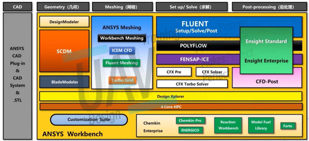
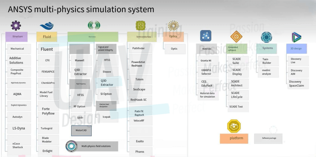
The software we used is ANSYS. Other simulation software includes COMSOL, domestic Wind Thunder and various open-source projects, etc., but ANSYS is the most useful one in my opinion: the ecology and community are also well built, and it is easy to find tutorials and discussions from various platforms.
ANSYS Production System: This is a graphic introduction of ANSYS CFX (one of the specific solvers within the ANSYS CFD suite)
Hardware Requirement
The hardware requirements are relatively high, each CPU core should be allocated at least 8G memory. If the memory is not enough, or the processor is not running fast, the computer performance is not enough, you can rent the servers of computing companies, so that service and quality can be guaranteed.
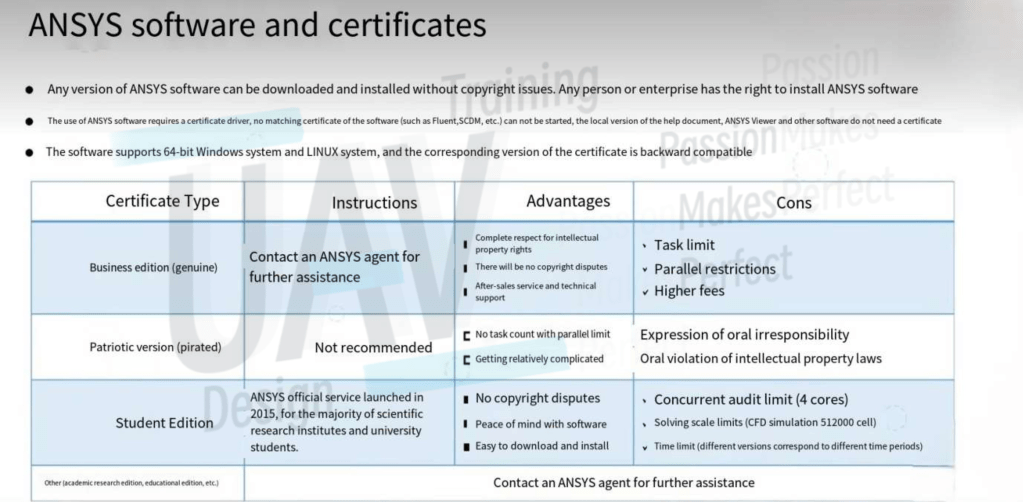
Software Certification
Basic Concepts


The Process of Simulation
- 3D Modeling
- Preprocessing (Log and console output are very important)
- Geometry:
- Repair geometry
- Optimize model
- Define special region (rotation)
- Create external flow field boundaries
- Define shared topology
- Name boundaries and fluid regions
- Grid Generation:
- Import geometry
- Local setting refinement
- Generate surface meshing
- Add shared topology (if not finished before)
- Set boundary layer
- Generate volume meshing
- Volume mesh repair and optimization
- Geometry:
- Solving (Log and console output are very important)
- Run calculation:
- Iteration limit
- Output interval limitation
- Time step setting (for transient calculations only)
- For all kinds of transient calculations, it is recommended to perform them on the basis of steady-state calculation data after the steady-state calculation reaches certain convergence conditions. For example, it is best to perform steady-state FMR simulation first, and then run transient calculation on this basis, which can greatly improve the simulation speed
- Convergence judgement Monitoring
- Initialization:
- Hybrid initialization
- FMR initialization
- Output settings:
- It should be noted that this refers to the output of various parameters during and after the simulation operation, rather than the visual output during post-processing
- Define output parameters
- Define output files
- Define output images
- Simulation setup:
- Model
- Fluid material settings
- Boundary type and boundary condition settings
- Cell zone condition settings
- Residual monitoring
- Verification:
- Unit: Gravity
- Grid quality: Skewness & Orthogonality
- Software setup:
- Process amount in computation
- GPU acceleration
- Working directory
- Parallel settings
- Language settings
- Run calculation:
- Post-processing and output
- Contour maps/ streamline plots etc.
- Pulse animation output of streamline plots
- Various data (e.g. drag, drag coefficients, etc.)
- Additional information output (e.g. location of center of lift)
